Infra-Red Light
| IR Led in the transmission mode. |
For example, at either end of the rainbow there is light we can't see. Below the red end is near infrared light, shorter in wavelength than the infrared we feel as heat. Above the violet end of the rainbow is near ultraviolet, longer in wavelength than the ultraviolet light that causes sunburn.
Because these invisible lights are so close to the visible light we can see, they act in many ways just like normal light. They can be focused with lenses, and cameras can see them.
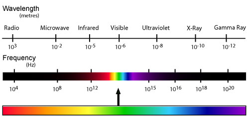 |
| Wavelength of light. |
 |
| IR-Led. |
Modulation
Modulation is the answer to make our signal stand out above the noise. With modulation we make the IR light source blink in a desired frequency. The IR receiver will be tuned to that frequency, so it can ignore everything else. We can consider this blinking as, attracting the receivers attention.

In the picture above it can be seen the modulated signal driving the IR LED of the transmitter, on the left side and the detected signal is coming out of the receiver, at the right side.
In serial communication we usually speak of 'marks' and 'spaces'. The 'space' is the default signal, which is the off state in the transmitter case. No light is emitted during the 'space' state. During the 'mark' state of the signal the IR light is pulsed on and off at a particular frequency. Frequencies between 30kHz and 60kHz are commonly used in consumer electronics.
At the receiver side a 'space' is represented by a high level of the receiver's output. A 'mark' is then automatically represented by a low level.
Note: The 'marks' and 'spaces' are not the 1-s and 0-s we want to transmit.
The real relationship between the 'marks' and 'spaces' and the 1-s and 0-s depends on the protocol that's being used.
The Transmitter
The transmitter usually is a battery powered handset. It should consume as little power as possible, and the IR signal should also be as strong as possible to achieve an acceptable control distance. Preferably it should be shock proof as well.
Many chips are designed to be used as IR transmitters. The older chips were dedicated to only one of the many protocols that were invented. Nowadays very low power microcontrollers are used in IR transmitters for the simple reason that they are more flexible in their use. When no button is pressed they are in a very low power sleep mode, in which hardly any current is consumed. The processor wakes up to transmit the appropriate IR command only when a key is pressed.
Quartz crystals are seldom used in such handsets. They are very fragile and tend to break easily when the handset is dropped. Ceramic resonators are much more suitable here, because they can withstand larger physical shocks. The fact that they are a little less accurate is not important.
The current through the LED (or LEDs) can vary from 100mA to well over 1A! In order to get an acceptable control distance the LED currents have to be as high as possible. A trade-off should be made between LED parameters, battery lifetime and maximum control distance. LED currents can be that high because the pulses driving the LEDs are very short. Average power dissipation of the LED should not exceed the maximum value though. You should also see to it that the maximum peek current for the LED is not exceeded. All these parameters can be found in the LED's data sheet.
 A simple transistor circuit can be used to drive the LED. A transistor with a suitable HFE and switching speed should be selected for this purpose.
The resistor values can simply be calculated using Ohm's law. Remember that the nominal voltage drop over an IR LED is approximately 1.1V.
 The normal driver, described above, has one disadvantage. As the battery voltage drops, the current through the LED will decrease as well. This will result in a shorter control distance that can be covered.
An emitter follower circuit can avoid this. The 2 diodes in series will limit the pulses on the base of the transistor to 1.2V. The base-emitter voltage of the transistor subtracts 0.6V from that, resulting in a constant amplitude of 0.6V at the emitter. This constant amplitude across a constant resistor results in current pulses of a constant magnitude. Calculating the current through the LED is simply applying Ohm's law again.
The Receiver
Many different receiver circuits exist on the market. The most important selection criteria are the modulation frequency used and the availability in our region.
 |
| The block diagram for an IR receiver. |
The received IR signal is picked up by the IR detection diode on the left side of the diagram. This signal is amplified and limited by the first 2 stages. The limiter acts as an AGC circuit to get a constant pulse level, regardless of the distance to the handset.
As you can see only the AC signal is sent to the Band Pass Filter (B.P.F.). The Band Pass Filter is tuned to the modulation frequency of the handset unit. Common frequencies range from 30kHz to 60kHz in consumer electronics.
The next stages are a detector, integrator and comparator. The purpose of these three blocks is to detect the presence of the modulation frequency. If this modulation frequency is present the output of the comparator will be pulled low.
As I said before, all these blocks are integrated into a single electronic component. There are many different manufacturers of these components on the market. And most devices are available in several versions each of which are tuned to a particular modulation frequency.
 |
| IR receiver and the connection mode into the circuit. |
There are several manufacturers of IR receivers on the market. Siemens, Vishay and Telefunken are the main suppliers here in Europe. Siemens has its SFH506-xx series, where xx denotes the modulation frequency of 30, 33, 36, 38, 40 or 56kHz. Telefunken had its TFMS5xx0 and TK18xx series, where xx again indicates the modulation frequency the device is tuned to. It appears that these parts have now become obsolete. They are replaced by the Vishay TSOP12xx, TSOP48xx and TSOP62xx product series.
Sharp, Xiamen Hualian and Japanese Electric are 3 Asian IR receiver producing companies. Sharp has devices with very cryptic ID names, like: GP1UD26xK, GP1UD27xK and GP1UD28xK, where x is related to the modulation frequency. Hualian has it's HRMxx00 series, like the HRM3700 and HRM3800. Japanese Electric has a series of devices that don't include the modulation frequency in the part's ID. The PIC-12042LM is tuned to 36.7kHz, and the PIC12043LM is tuned to 37.9kHz.
Conclusion
This theory who describe the operation of IR remote control systems is intended for use in consumer electronics.
One of the issues not covered here is security. Security is not important if I want to control my VCR or TV set. But when it comes to opening doors or cars, it literally becomes a 'key' feature.
This page only described the basic theory of operation for IR remote control. It is not describe the protocols that are involved in communication between transmitter and receiver. Many protocols are designed by different manufacturers.
In the next articles, I will present the protocols RC5 and RC6 designed by Philips, used for infrared communication.