 |
In the first experiment that we are going to do, with PIC16F628A, we will show how to set M.C.U (MicroController Unit) to make all ports output (in 1 logic, meaning in this case 5vcc).
The output will be displayed on L.E.Ds, connected to PORTA and PORTB. Series resistors with L.E.Ds are able to limit the current through the LED to meet the data catalog (max. 20 ~ 25mA with a minimum voltage of 1.8 V to open junction P.N). |
 |
In this experiment we will show how to set MCU to make a LED blinking. PORTB will be used to show that.
Button S1 and (pull-up) resistance with value of 4.7 K will provide the manual reset mode the microcontroller. ICSP connector provides the connection between the programmer (PicKit 2) and microcontroller (PIC6F628A). |
 |
In this experiment we will show how to set MCU to count 8-bit in binary mode. The Counter will counts from 0(00h) to 255(FFh) with 1sec delay between each count. The output will be displayed on 8 L.E.Ds connected to PORT RB.0~RB.7
Button S1 and (pull-up) resistance with value of 4.7 K will provide the manual reset mode to the microcontroller. ICSP connector provides the connection between the programmer (PicKit 2) and microcontroller (PIC16F628A). |
 |
This example illustrates how the watch-dog timer should not be used. A command used for resetting this timer is intentionally left out in the main program loop, thus enabling the microcontroller to be reset. As a result, the microcontroller will be reset all the time, which is reflected as PORT RB.0~RB.7 LED blinking.
Button S1 and (pull-up) resistance with value of 4.7 K will provide the manual reset mode to the microcontroller. |
 |
In this experiment we will work with interrupt which are enabled after the timer register TMR1 (TMR1H, TMR1L) overflow occurs.
As result combination of bits will be changing on PORT RB.0~RB.7. ICSP connector provides the connection between the programmer (PicKit 2) and microcontroller (PIC16F628A). |
 |
In this experiment we will make a demonstration with button library. The PORTB is used for this experiment (as output, for a leds) and RA6 (as imput, for button S2).
As usualy, button S1 and (pull-up) resistance with value of 4.7 K will provide the manual reset mode to the microcontroller. ICSP connector provides the connection between the programmer (PicKit 2) and microcontroller (PIC16F628A). |
 |
In this experiment we will use the CCP1 as a PWM to control the power to a L.E.D. PWM stands for the Pulse Width Modulation where the width of a digital waveform is varied to control the power delivered to a load (in this case an L.E.D).
|
 |
Like in the last Lesson, nr.07, we will work with CCP1 in PWM mode, to control the luminous intensity of a L.E.D, but here we will not use buttons to vary the width form of our signal. The pulse width will automatically vary between 0% and 100% and vice versa.
|
 |
In this experiment we will work again with PWM, but this time, as a consumer, I will use a DC (Direct Current) motor. To avoid burning RB3 port, due to high consumption of the motor, consumption which can not be given by the port of the microcontroller, we will use an extension consisting of a transistor (our case, BC547/NPN) connected in switching mode (ON / OFF ).
|
 |
This time we will implement software PWM mode, to control the light intensity of an RGB Led (Red Green Blue, which represents a pixel) .PORT RA0~RA2 and PORT RB0~RB2 will be used for this experiment.
Port B is used, to see more easier transitions between RBG colors. |
 |
In this experiment we will learn how to use more than one 7-segment Led display, connected simultaneously at the microcontroller port, using multiplexing technique. In the current experiment will interface four digit common cathode to PORT B, the command part, and to PORT A, the control of digits. The multiplexing circuit is configured on the breadboard, being composed of four NPN transistor and some resistance.
|
 |
The basic technique is the same like the last lesson except fact that we have added a counter which counts between 0000 and 9999. Our counter increments with 1 second delay.
All 7-segment displays are connected to PORTB (RB0..RB7, segment A to RB0, segment B to RB1, etc.) with refresh via pins RA0..RA3 on PORTA. |
 |
Today Lesson is different from the last one, by the presence of two buttons and manually increment .
All 7-segment displays are connected to PORTB (RB0..RB7, segment A to RB0, segment B to RB1, etc.) with refresh via pins RA0..RA3 on PORTA. |
 |
In this Lesson, we will make a digital temperature meter using DS18B20. The connection between temperature sensor and microcontroller will be done through a single wire. This is advantage of the temperature sensor model. The temperature value will be displayed on 4 digits-with 7 segment, in multiplexed mod of course.
|
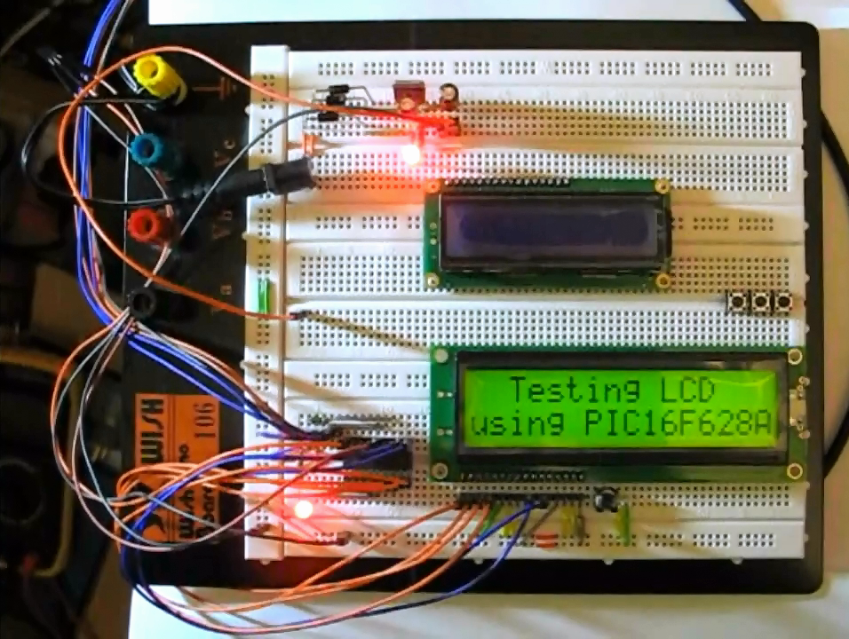 |
The purpose of this experiment is to interface an LCD 2x16 characters (compatible with standard HD44780) to PIC16F628A in 4-bit mode. This means the data transfer will use just 4 pins of the microcontroller. No additional hardware configuration is required. In the current experiment we are displaying a text, on the 2 x16 LCD. The circuit diagram is presented below.
|
 |
The communication technique with the LCD is the same like the last lesson, and for the current experiment we have added a counter which counts between 0000 and 9999. Our counter increments with 1 second delay.
The connections with LCD is made as follows: D4 with RB0, D5 with RB1, D6 with RB2, D7 with RB3, RS with RB4 and EN with RB5. |
 |
In this experiment we will work with alphanumeric LCD and push button.
Communication with LCD will be performed through 4-bits and connections is made as follows: D4 with RB0, D5 with RB1, D6 with RB2, D7 with RB3, RS with RB4 and EN with RB5. The Push button is connected to PORT RA4 (for increment) and PORT RA6 (for decrement). Of course both button have pull-up resistors (4k7). |
 |
In this experiment we will work with temperature sensor DS18B20, but this time results will be displayed on 2x16 LCD.
Communication with LCD will be performed through 4-bits and connections is made as follows: D4 with RB0, D5 with RB1, D6 with RB2, D7 with RB3, RS with RB4 and EN with RB5. Data pin of DS18B20 is connected to PORT RA1 and we also use pull-up resistors (4k7 ohm), for the communication with temperature sensor to be performed. |
 |
In this experiment we will work with internal EEPROM Memory and I'll show how to write and read information on it helped by a little menu, displayed on the LCD 2x16 characters.
|
 |
In this experiment we will work with sounds and I'll show how to generate and make sound helped by microcontroller and some buttons.
|
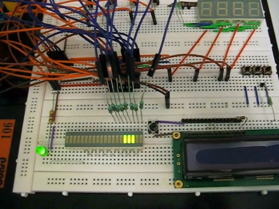
And now some pictures with the breadboard during the experiments.


