Menu

all about electronic and microcontrollers
Showing posts with label LCD. Show all posts

Saturday, November 17, 2018

DHT22 & LCD Shield

In this article I will describe to you, how to develop a home weather station using the DHT22 temperature/humidity sensor.

TECHNICAL DETAILS

Model:
Power supply:
DHT22
3.3-6V DC (2.5mA max current use during conversion (while requesting data))
Output signal:
Digital signal via single-bus
Sensing element:
Polymer capacitor
Operating range:
Humidity: 0-100%RH;
Temperature: -40~80Celsius
Accuracy:
Humidity +-2%RH(Max +-5%RH);
Temperature <+-0.5 Celsius
Resolution or sensitivity:
Humidity 0.1%RH;
Temperature 0.1Celsius
Repeatability:
Humidity +-1%RH;
Temperature+-0.2Celsius
Humidity hysteresis:
+-0.3%RH
Long-term Stability:
+-0.5%RH/year
Sensing period:
Average: 2s
Interchangeability:
fully interchangeable
Dimensions:
Small size 14*18*5.5mm;
Big size 22*28*5mm
Weight (just the DHT22):
2.4g

Hardware setup:
The development board used for this experiment will be the Arduino UNO and the measured values will be displayed on 1602 LCD Keypad Shield board.

DHT22 is a low-cost digital temperature and humidity sensor. It uses a capacitive humidity sensor and a thermistor to measure the surrounding air, and generate out a digital signal on the data pin (which means no analog input pins needed). It's fairly simple to use, but requires careful timing to collect data. The only real downside of this sensor is you can only get new data from it once every 2 seconds, so when using DHT22 library, sensor readings can be up to 2 seconds old.

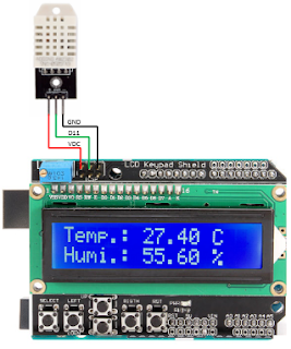
Simply connect the first pin on the left to 3-5V power, the second pin to your data input pin and the rightmost pin to ground. Although it uses a single-wire to send data it is not Dallas One Wire compatible! If you want multiple sensors, each one must have its own data pin.

In my particular case 1602 LCD Keypad Shield ICSP connector (VCC, D11, GND) was the easiest way to connect my DHT22 sensor. Keypad functionality wouldn’t be used on this article.


Some pictures from the surgery.


On below video we can see the Arduino UNO board in action.


Software:
The program is written in Arduino IDE software (version v1.8.7).

Libraries used:

Below is presented the software approach for this project:

/*
'*******************************************************************************
'  Project name: DHT22 & LCD Shield
'  Description:
'   In this experiment i will describe to you, how to develop a home weather 
'   station using the DHT22 temperature/humidity sensor.       
'   Temperature will be displayed in Celsius Degree and the Umidity in percent
'   The delay between two consecutive reads is set to about 2.1 seconds.
'          Ex. of viewing display: 
'               ________________                         
'              |TEMP.: 24.60 C  |     
'              |Humy.: 54.40 %__|
'
'   Hardware configuration is:
'             DHS22 is connected to 1602 LCD Keypad Shield ICSP connector (vdc, d11,gnd).
'             The 1602 LCD Keypad Shield board is inserted into Arduino UNO standard connectors.
'
'  Written by:
'          Aureliu Raducu Macovei, 2018 (www.electronicexperiments.blogspot.com).
'
'  Test configuration:
'    MCU:                        ATmega328P;
'    Test.Board:                 Arduino UNO;
'    SW:                         Arduino IDE software (version v1.8.7);
'                                DHT Library from Arduino official website:
'                                https://playground.arduino.cc/Main/DHTLib
'*******************************************************************************
 */
 
#include LiquidCrystal.h // includes the LiquidCrystal Library
#include DHT22.h         // includes the DHT22 Library

#define DHT22_PIN 11

// Setup a DHT22 instance
DHT22 myDHT22(DHT22_PIN);

// initialize the library by associating any needed LCD interface pin
// with the arduino pin number it is connected to
const int rs = 8, en = 9, d4 = 4, d5 = 5, d6 = 6, d7 = 7;
LiquidCrystal lcd(rs, en, d4, d5, d6, d7);

void setup() {
  // set up the LCD's number of columns and rows:
  lcd.begin(16, 2);
  lcd.setCursor(0,0);
  lcd.print("    -DHT22 &-   ");
  lcd.setCursor(0,1);
  lcd.print("  --LCD 2x16--  ");
  delay(5000);
  lcd.setCursor(0,0);
  lcd.print("                ");
  delay(100);
  lcd.setCursor(0,1);
  lcd.print("                ");
  delay(500);
}

void loop(void)
{ 
  DHT22_ERROR_t errorCode;
  // The sensor can only be read from every 1-2s, and requires a minimum
  // 2s warm-up after power-on.
  delay(2100);

  errorCode = myDHT22.readData();
  switch(errorCode)
  {
    case DHT_ERROR_NONE:
      lcd.setCursor(0,0);     // Set the first row (location at which subsequent text written to the LCD will be displayed)
      lcd.print("Temp.: ");   // Print "Temp.:" on the LCD
      lcd.print(myDHT22.getTemperatureC());     // Print string temperature
      lcd.print(" C");                          // Prints "C" on the LCD
      lcd.setCursor(0,1);     // Set the second row (location at which subsequent text written to the LCD will be displayed)
      lcd.print("Humi.: ");   // Print "Humi.:" on the LCD
      lcd.print(myDHT22.getHumidity());         // Print string humidity
      lcd.print(" %");        // Prints "%" on the LCD
      break;
    case DHT_ERROR_CHECKSUM:
      lcd.print("check sum error ");
      lcd.print(myDHT22.getTemperatureC());
      lcd.print("C ");
      lcd.print(myDHT22.getHumidity());
       lcd.println("%");
      break;
    case DHT_BUS_HUNG:
      lcd.println("BUS Hung ");
      break;
    case DHT_ERROR_NOT_PRESENT:
      lcd.println("Not Present ");
      break;
    case DHT_ERROR_ACK_TOO_LONG:
      lcd.println("ACK time out ");
      break;
    case DHT_ERROR_SYNC_TIMEOUT:
      lcd.println("Sync Timeout ");
      break;
    case DHT_ERROR_DATA_TIMEOUT:
      lcd.println("Data Timeout ");
      break;
    case DHT_ERROR_TOOQUICK:
      lcd.println("Polled to quick ");
      break;
  }
}

Saturday, March 29, 2014

Real Time Clock [DS1307 with Set Functions] & DS18B20

Hello dear fellows, today I will share with you this amazing project which will highlights what can be done with DS1307.
The Real Time Clock (RTC) chip produced by Maxim is a popular and relatively low cost solution for creating a room clock.

Features:
  1. Real-Time Clock (RTC) Counts Seconds, Minutes, Hours, Date of the Month, Month, Day of the week, and Year with Leap-Year Compensation Valid Up to 2100.
  2. 56-Byte, Battery-Backed, General-Purpose RAM with Unlimited Writes.
  3.  I2C Serial Interface.
  4. Programmable Square-Wave Output Signal.
  5.  Automatic Power-Fail Detect and Switch Circuitry.
  6. Consumes Less than 500nA in Battery-Backup Mode with Oscillator Running.
  7.  Operating temperature range for commercial use only: 0°C to +70°C.
  8. Optional Industrial Temperature Range: -40°C to +85°C.
  9. Available in 8-Pin Plastic DIP or SO.
As can be seen from it's datasheet, the communications are achieved via I2C (designed by Philips) protocol.

Hardware setup:
In the current article I intend to display the clock information and room temperature, on the LCD with 2x16 characters. Also trough four buttons, I will try to be able to set all the times variable, stored, in DS1307 chip.
Physical realization is carried out on the breadboard with 2420 dots.


Trough this video I would like to let you know precisely, how are things going.


Below I present the timing diagram for I2C signal transmitted on pins 5-6 of the DS1307.

Data Transfer on I2C Serial Bus.

Pin Configurations.
The diagram block.


For more details, please study the DS1307 datasheet.

Circuit Diagram:
Difficulty level of the electronic scheme, is low. The microcontroller used is PIC16F876A.
S1 is the master reset button, R1 is the resistor of pull-up button.
Cristal quartz by 8 MHz, is used.
ICSP connector is used to program the microcontroller.
Trough R7 we can adjust the contrast for LCD with 2x16 characters.
R6 adjusts the current through the LED LCD (light intensity of it).
R2-R5, R8-R10 are resistors for pull-up.

I personally designed the physical pcb circuit for DS1307, through the five pins,  pcb communicate with the breadboard in this way (GND, SQW, SCL, SDA, 5VDC). In this project i didn't use SQW pin.


The electronic scheme is built in Eagle Cad , free version.

Software:
The program is written in mikroC Pro for PIC 2013 (version v6.0.0).
Below is my software version:
/*
'*******************************************************************************
'  Project name: Real Time Clock [DS1307 with Set Functions] & DS18B20
'  Description:
'          Trough the current experiment we wish to succed the next task:
'          Display on LCD 2x16 character the clock and room temperature.
'          Setting trough four buttons: the minutes, hours, date of the month,
'          month, day of the week, and year.
'
'          Our clock displays as shown below(but just in display time,
'          not in set mode).
'          Ex. of viewing on 2x16 LCD characters:
'          Display time, mode:             Set time, mode (cursor on):
'          ------------------              ------------------
'          |Sat, 03 Dec 2011|              |Sat, 03 12  2011|
'          |21:32:03 +26,1*C|              |21:32:03        |
'          ------------------              ------------------
'
'          Hardware configuration is:
'             IC ds1307 is connected with our microcontroller trough RC3=SCL,
'             RC4=SDA (I2C Connections), RB0,RB1,RB4-RB7 are assigned to LCD (2x16)
'             DS18B20 is assigned to RC7,
'             Buttons Menu: RC0= Increment value,
'                           RC1= Decrement value,
'                           RC2= Change cursor position,
'                           RC5= Enter.(It goes to set functions or exit from set
'                                functions)
'  Written by:
'          Aureliu Raducu Macovei, 2014.
'  Test configuration:
'    MCU:                        PIC16F876A;
'    Test.Board:                 WB-106 Breadboard 2420 dots;
'    SW:                         MikroC PRO for PIC 2013 (version v6.0.0);
'  Configuration Word:
'    Oscillator:                 HS (8Mhz)on pins 9 and 10;
'    Watchdog Timer:             OFF;
'    Power up Timer:             OFF;
'    Browun Out Detect:          ON;
'    Low Voltage Program:        Disabled;
'    Data EE Read Protect:       OFF;
'    Flash Program Write:        Write Protection OFF;
'    Background Debug:           Disabled;
'    Code Protect:               OFF
'*******************************************************************************
*/

// LCD module connections
sbit LCD_RS at RB0_bit;                 // LCD_RS assigned to PORT RB0;
sbit LCD_EN at RB1_bit;                 // LCD_EN assigned to PORT RB1;
sbit LCD_D4 at RB4_bit;                 // LCD_D4 assigned to PORT RB4;
sbit LCD_D5 at RB5_bit;                 // LCD_D5 assigned to PORT RB5;
sbit LCD_D6 at RB6_bit;                 // LCD_D6 assigned to PORT RB6;
sbit LCD_D7 at RB7_bit;                 // LCD_D7 assigned to PORT RB7;

sbit LCD_RS_Direction at TRISB0_bit;    // LCD_RS assigned to TRIS B0;
sbit LCD_EN_Direction at TRISB1_bit;    // LCD_EN assigned to TRIS B1;
sbit LCD_D4_Direction at TRISB4_bit;    // LCD_D4 assigned to TRIS B4;
sbit LCD_D5_Direction at TRISB5_bit;    // LCD_D5 assigned to TRIS B5;
sbit LCD_D6_Direction at TRISB6_bit;    // LCD_D6 assigned to TRIS B6;
sbit LCD_D7_Direction at TRISB7_bit;    // LCD_D7 assigned to TRIS B7;
// End LCD module connections

unsigned char sec,min1,hr,week_day,day,mn,year;
//--------------------- Reads time and date information from RTC (DS1307)
void Read_Time(char *sec, char *min, char *hr, char *week_day, char *day, char *mn, char *year)
{
 I2C1_Start();                    // Issue start signal
 I2C1_Wr(0xD0);                   // Address DS1307, see DS1307 datasheet
 I2C1_Wr(0);                      // Start from address 0
 I2C1_Repeated_Start();           // Issue repeated start signal
 I2C1_Wr(0xD1);                   // Address DS1307 for reading R/W=1
 *sec =I2C1_Rd(1);                // Read seconds byte
 *min =I2C1_Rd(1);                // Read minutes byte
 *hr =I2C1_Rd(1);                 // Read hours byte
 *week_day =I2C1_Rd(1);           // Read week day byte
 *day =I2C1_Rd(1);                // Read day byte
 *mn =I2C1_Rd(1);                 // Read mn byte
 *year =I2C1_Rd(0);               // Read Year byte
 I2C1_Stop();                     // Issue stop signal
}
//-----------------write time routine------------------
void Write_Time(char minute, char hour ,char weekday,char day,char month,char year)
{
 char tmp1, tmp2;

 tmp1 = minute / 10;               //Write tens of minute
 tmp2 = minute % 10;               //Write unit of minute
 minute = tmp1 * 16 + tmp2;        //Includes all value

 tmp1 = hour / 10;                 //Write tens of hour
 tmp2 = hour % 10;                 //Write unit of hour
 hour = tmp1 * 16 + tmp2;          //Includes all value

 tmp1 = weekday / 10;              //Write tens of weekday
 tmp2 =  weekday % 10;             //Write unit of weekday
 weekday = tmp1 *16 +tmp2;         //Includes all value

 tmp1 = day / 10;                  //Write tens of day
 tmp2 =  day % 10;                 //Write unit of day
 day = tmp1 *16 +tmp2;             //Includes all value

 tmp1 = month / 10;                //Write tens of month
 tmp2 =  month % 10;               //Write unit of month
 month = tmp1 *16 +tmp2;           //Includes all value

 tmp1 = year / 10;                 //Write tens of year
 tmp2 =  year % 10;                //Write unit of year
 year = tmp1 *16 +tmp2;            //Includes all value

 I2C1_Start();          // issue start signal
 I2C1_Wr(0xD0);         // address DS1307
 I2C1_Wr(0);            // start from word at address (REG0)
 I2C1_Wr(0x80);         // write $80 to REG0. (pause counter + 0 sec)
 I2C1_Wr(minute);       // write minutes word to (REG1)
 I2C1_Wr(hour);         // write hours word (24-hours mode)(REG2)
 I2C1_Wr(weekday);      // write 6 - Saturday (REG3)
 I2C1_Wr(day);          // write 14 to date word (REG4)
 I2C1_Wr(month);        // write 5 (May) to month word (REG5)
 I2C1_Wr(year);         // write 01 to year word (REG6)
 I2C1_Wr(0x80);         // write SQW/Out value (REG7)
 I2C1_Stop();           // issue stop signal

 I2C1_Start();          // issue start signal
 I2C1_Wr(0xD0);         // address DS1307
 I2C1_Wr(0);            // start from word at address 0
 I2C1_Wr(0);            // write 0 to REG0 (enable counting + 0 sec)
 I2C1_Stop();           // issue stop signal
}
//-------------------- Formats date and time---------------------
void Transform_Time(char  *sec, char *min, char *hr, char *week_day, char *day, char *mn, char *year)
{
  *sec  =  ((*sec & 0x70) >> 4)*10 + (*sec & 0x0F);
  *min  =  ((*min & 0xF0) >> 4)*10 + (*min & 0x0F);
  *hr   =  ((*hr & 0x30) >> 4)*10 + (*hr & 0x0F);
  *week_day =(*week_day & 0x07);
  *day  =  ((*day & 0xF0) >> 4)*10 + (*day & 0x0F);
  *mn   =  ((*mn & 0x10) >> 4)*10 + (*mn & 0x0F);
  *year =  ((*year & 0xF0)>>4)*10+(*year & 0x0F);
 }
//------------------------Display time---------------------------
char *txt,*mny;
void Display_Time(char sec, char min, char hr, char week_day, char day, char mn, char year)
{
 switch(week_day)
 {
  case 1: txt="Mon"; break;       // Monday;
  case 2: txt="Tue"; break;       // Tuesday;
  case 3: txt="Wed"; break;       // Wednesday;
  case 4: txt="Thu"; break;       // Thursday;
  case 5: txt="Fri"; break;       // Friday;
  case 6: txt="Sat"; break;       // Saturday;
  case 7: txt="Sun"; break;       // Sunday;
  }

 LCD_Out(1, 1,txt);
 LCD_chr(1, 4,',');

 switch(mn)
 {
  case  1: mny="Jan"; break;
  case  2: mny="Feb"; break;
  case  3: mny="Mar"; break;
  case  4: mny="Apr"; break;
  case  5: mny="May"; break;
  case  6: mny="Jun"; break;
  case  7: mny="Jul"; break;
  case  8: mny="Aug"; break;
  case  9: mny="Sep"; break;
  case 10: mny="Oct"; break;
  case 11: mny="Nov"; break;
  case 12: mny="Dec"; break;
  }

 Lcd_Chr(1, 6, (day / 10) + 48);    // Print tens digit of day variable
 Lcd_Chr(1, 7, (day % 10) + 48);    // Print oness digit of day variable
 Lcd_Out(1, 9,mny);
 Lcd_out(1,13,"20");
 Lcd_Chr(1,15, (year / 10)  + 48);  // we can set year 00-99 [tens]
 Lcd_Chr(1,16, (year % 10)  + 48);  // we can set year 00-99 [ones]
 Lcd_Chr(2, 1, (hr / 10)  + 48);
 Lcd_Chr(2, 2, (hr % 10)  + 48);
 Lcd_Chr(2, 3,':');
 Lcd_Chr(2, 4, (min / 10) + 48);
 Lcd_Chr(2, 5, (min % 10) + 48);
 Lcd_Chr(2, 6,':');
 Lcd_Chr(2, 7, (sec / 10) + 48);
 Lcd_Chr(2, 8, (sec % 10) + 48);
 }
//-------------------Display Time in Set mode--------------------
char minute1,hour1,weekday1,month1;
char minute,hour,weekday,day1,month,year1;
void Display_Time_SetMode()
{
 switch(weekday1)
 {
  case 1: txt="Mon"; break;       // Monday;
  case 2: txt="Tue"; break;       // Tuesday;
  case 3: txt="Wed"; break;       // Wednesday;
  case 4: txt="Thu"; break;       // Thursday;
  case 5: txt="Fri"; break;       // Friday;
  case 6: txt="Sat"; break;       // Saturday;
  case 7: txt="Sun"; break;       // Sunday;
  }

 LCD_Out(1, 1,txt);
 LCD_chr(1, 4,',');

 Lcd_Chr(1, 6, (day1 / 10)   + 48);    // Print tens digit of day variable
 Lcd_Chr(1, 7, (day1 % 10)   + 48);    // Print oness digit of day variable
 Lcd_chr(1,10, (month1 / 10) + 48);    // Print tens digit of month variable
 Lcd_chr(1,11, (month1 % 10) + 48);    // Print oness digit of month variable
 Lcd_out(1,13,"20");
 Lcd_Chr(1,15, (year1 / 10)  + 48);    // Print tens digit of year variable
 Lcd_Chr(1,16, (year1 % 10)  + 48);    // Print oness digit of year variable
 Lcd_Chr(2, 1, (hour1 / 10)  + 48);    // Print tens digit of hour variable
 Lcd_Chr(2, 2, (hour1 % 10)  + 48);    // Print oness digit of hour variable
 Lcd_Chr(2, 3,':');
 Lcd_Chr(2, 4, (minute1 / 10) + 48);   // Print tens digit of minute variable
 Lcd_Chr(2, 5, (minute1 % 10) + 48);   // Print oness digit of minute variable
 Lcd_Chr(2, 6,':');
 Lcd_Chr(2, 7, (0 / 10) + 48);
 Lcd_Chr(2, 8, (0 % 10) + 48);
}

char SPos;
//----------------------Move cursor routine----------------------
char index;
void movecursor()
{
 char i,moveto;
 if(SPos==0)
 lcd_cmd(_lcd_first_row);  // set weekday;
 if(SPos==1)
 lcd_cmd(_lcd_first_row);  // set day;
 if(SPos==2)
 lcd_cmd(_lcd_first_row);  // set month;
 if(SPos==3)
 lcd_cmd(_lcd_first_row);  // set year;
 if(SPos==4)
 lcd_cmd(_lcd_second_row); // set hours;
 if(SPos==5)
 lcd_cmd(_lcd_second_row); // set minutes;

 moveto = 2;
 switch(index)
 {
  case 0: moveto = 2;break;
  case 1: moveto = 6;break;
  case 2: moveto =10;break;
  case 3: moveto =15;break;
  case 4: moveto = 1;break;
  case 5: moveto = 4;break;
  }
  for(i=1; i<= moveto; i++)
  lcd_cmd(_lcd_move_cursor_right);
}
//------------Start Buttons routine--------------;
char setuptime=0;
void Press_Switch()
{
 if(setuptime)
 {
  if(Button(&portc,2,1,0))         // If buttons at port c2 is pressed
  {
   delay_ms(200);
   SPos++;
   if(SPos>5)
   SPos=0;
   index++;
   if(index > 5)
   index=0;
   movecursor();
   }
  //-----------------------------case mode to set all values---------------------
  switch(SPos)
  {
   case 0: if(button(&portc,0,1,0))       // If buttons at port c0 is pressed
           {
            Delay_ms(200);
            weekday1++;
            if(weekday1 > 7)
            weekday1=1;
            Display_Time_SetMode();
            index=0;
            movecursor();
            }

           if(button(&portc,1,1,0))       // If buttons at port c1 is pressed
           {
            Delay_ms(200);
            weekday1--;
            if(weekday1 < 1)
            weekday1=7;
            Display_Time_SetMode();
            index=0;
            movecursor();
            }
           break;
   case 1: if(button(&portc,0,1,0))       // If buttons at port c0 is pressed
           {
            Delay_ms(200);
            day1++;
            if(day1 > 31)
            day1 = 1;
            Display_Time_SetMode();
            index=1;
            movecursor();
            }

           if(button(&portc,1,1,0))        // If buttons at port c1 is pressed
           {
            Delay_ms(200);
            day1--;
            if(day1 < 1)
            day1 = 31;
            Display_Time_SetMode();
            index=1;
            movecursor();
            }
           break;
   case 2: if(button(&portc,0,1,0))         // If buttons at port c0 is pressed
           {
            Delay_ms(200);
            month1++;
            if(month1 > 12)
            month1 = 1;
            Display_Time_SetMode();
            index=2;
            movecursor();
            }

           if(button(&portc,1,1,0))          // If buttons at port c1 is pressed
           {
            Delay_ms(200);
            month1--;
            if(month1 < 1)
            month1 = 12;
            Display_Time_SetMode();
            index=2;
            movecursor();
            }
           break;
   case 3: if(button(&portc,0,1,0))           // If buttons at port c0 is pressed
           {
            Delay_ms(200);
            year1++;
            if(year1 > 99)
            year1 = 1;
            Display_Time_SetMode();
            index=3;
            movecursor();
            }

           if(button(&portc,1,1,0))           // If buttons at port c1 is pressed
           {
            Delay_ms(200);
            year1--;
            if(year1 < 1)
            year1 = 99;
            Display_Time_SetMode();
            index=3;
            movecursor();
            }
           break;
   case 4: if(button(&portc,0,1,0))            // If buttons at port c0 is pressed
           {
            Delay_ms(200);
            hour1++;
            if(hour1 > 23)
            hour1 = 0;
            Display_Time_SetMode();
            index=4;
            movecursor();
            }

           if(button(&portc,1,1,0))            // If buttons at port c1 is pressed
           {
            Delay_ms(200);
            hour1--;
            if(hour1 > 23)
            hour1 = 0;
            Display_Time_SetMode();
            index=4;
            movecursor();
            }
           break;
   case 5: if(button(&portc,0,1,0))            // If buttons at port c0 is pressed
           {
            Delay_ms(200);
            minute1++;
            if(minute1 > 59)
            minute1 = 0;
            Display_Time_SetMode();
            index=5;
            movecursor();
            }

           if(button(&portc,1,1,0))             // If buttons at port c1 is pressed
           {
            Delay_ms(200);
            minute1--;
            if(minute1 > 59)
            minute1 = 0;
            Display_Time_SetMode();
            index=5;
            movecursor();
            }
           break;
   }                            // end "if is in switch mode"
  }                             // end "if is in setup"

 if(button(&portc,5,1,0))                      // If buttons at port c5 is pressed
 {
  Delay_ms(200);
  setuptime = !setuptime;
  if(SetupTime)
  {
   lcd_cmd(_lcd_clear);
   lcd_cmd(_lcd_blink_cursor_on);
   weekday1=week_day;
   hour1=hr;
   minute1=min1;
   day1=day;
   month1=mn;
   year1=year;
   Display_Time_SetMode();
   SPos=0;
   index=0;
   movecursor();
   }
   else
   {
   Lcd_Cmd(_Lcd_clear);
   lcd_cmd(_lcd_cursor_off);
   weekday=weekday1;
   hour=hour1;
   minute=minute1;
   day=day1;
   month=month1;
   year=year1;
   Write_time(minute,hour,weekday,day,month,year);
   }
  }
 }
//----------------------End Buttons Routine-------------------
//------------------Temperature sensor routines---------------
const unsigned short TEMP_RESOLUTION = 12;     // 9 for DS1820 and 12 for DS18B20
char *text = "000,0";
unsigned temp;
void Display_Temperature(unsigned int temp2write)
{
 const unsigned short RES_SHIFT = TEMP_RESOLUTION - 8;
 char temp_whole;
 unsigned int temp_fraction;
 unsigned short isNegative = 0x00;

 // Check if temperature is negative
 if (temp2write & 0x8000)
 {
  text[0] = '-';
  temp2write = ~temp2write + 1;
  isNegative = 1;
  }
  // Extract temp_whole
  temp_whole = temp2write >> RES_SHIFT ;
  // Convert temp_whole to characters
  if (!isNegative){
  if (temp_whole/100)
  text[0] = temp_whole/100  + 48;                // Extract hundreds digit
  else
  text[0] = '+';
  }
  text[1] = (temp_whole/10)%10 + 48;             // Extract tens digit
  text[2] =  temp_whole%10     + 48;             // Extract ones digit
  // Extract temp_fraction and convert it to unsigned int
  temp_fraction  = temp2write << (4-RES_SHIFT);
  temp_fraction &= 0x000F;
  temp_fraction *= 625;
  // Convert temp_fraction to characters
  text[4] =  temp_fraction/1000 + 48;         // Extract thousands digit
  // Print temperature on LCD
  Lcd_Out(2, 10,text);
  lcd_chr(2, 15,0xB2);                        // Ascii code for degrees symbol;
  Lcd_chr(2, 16,'C');                         // Show symbol "C" from Celsius
}
//----------------Read and display Temperature from DS18B20--------------
void Read18b20()
{
 //--- Perform temperature reading
 Ow_Reset(&PORTC, 7);                           // Onewire reset signal;
 Ow_Write(&PORTC, 7, 0xCC);                     // 0xCC Issue command SKIP_ROM;
 Ow_Write(&PORTC, 7, 0x44);                     // Issue command CONVERT_T;
 Delay_us(700);                                 // delay 0,7s (required for signal
                                                // processing);
 Ow_Reset(&PORTC, 7);                           // Onewire reset signal;
 Ow_Write(&PORTC, 7, 0xCC);                     // Issue command SKIP_ROM;
 Ow_Write(&PORTC, 7, 0xBE);                     // Issue command READ_SCRATCHPAD;

 temp = Ow_Read(&PORTC, 7);                     // Next Read Temperature, read Byte
                                                // 0 from Scratchpad;
 temp = (Ow_Read(&PORTC, 7) << 8) + temp;       // Then read Byte 1 from Scratchpad
                                                // and shift 8 bit left and add the Byte 0;
 //--- Format and display result on Lcd
 Display_Temperature(temp);                     // Call Display_Temperature;
 }
//------------------Temperature sensor routines---------------
void Init_Main()
{
 CMCON |=7;             //TURN OFF ANALOGUE COMPARATOR AND MAKE PORTA TO DIGITAL I/O;

 I2C1_Init(100000);         // initialize I2C
 Lcd_Init();                // Initialize LCD
 Lcd_Cmd(_LCD_CLEAR);       // Clear LCD display
 Lcd_Cmd(_LCD_CURSOR_OFF);  // Turn cursor off

 Display_Time(sec, min1, hr, week_day, day, mn, year);

 !setuptime=1;
 index=0;
 SPos=0;
 }
//-----------------Here we have the Main Routine----------------
void main()
{
 Init_Main();
 while (1)                                                 // While loop
 {
  Read_Time(&sec,&min1,&hr,&week_day,&day,&mn,&year);      // read time from RTC(DS1307)
  Transform_Time(&sec,&min1,&hr,&week_day,&day,&mn,&year); // Transform time
  Press_Switch();                                          // Check buttons;
  if(!setuptime)
  {
   Display_Time(sec, min1, hr, week_day, day, mn, year);
   Read18b20();
   }
  }
}

Monday, August 8, 2011

Distance Sensor Sharp 2YOA21 & LCD

The distance sensor produced by Sharp is a popular and relatively low cost solution for measuring distance. The sensor can be used also for measuring the rightness or color (in very limited extent) but in this article we will talk only about measuring distances.
In the current experiment we will use the 2YOA21 model and the characteristics of this sensor are:
  1. Minimum Measuring Distance = 10cm;
  2. Maximum Measuring Distance = 80cm;
  3. Infrared Proximity Sensor;
  4. Analog output inversely proportional to distance;
  5. Sensor is Ratiometric;
  6. Operating Supply Voltage = 4.5V to 5.5V;
  7. Average Supply Current – Typical = 30mA;
  8. Response Time = 38 ± 10ms.
Obviously there are several versions of sensors which are capable to measure distances shorter or longer, depending on needs.
Examples of sensors are:
  • Sharp Distance Sensor GP2D120 (4-30cm);
  • Sharp Distance Sensor GP2Y0A21 (10-80cm);
  • Sharp Distance Sensor GP2Y0A02 (20-150cm).
The data signal of sensor 2YOA21 are sent in analog way and the connection made with the microcontroller is very simple. The analog output varies from 3.1V at 10cm to 0.3V at 80cm.

Hardware setup:
In the current article I intend to display the measured distance, between sensor and some object, on the LCD with 2x16 characters.
Physical realization is carried out on the breadboard with 2420 dots.


Trough this video I would like to share the situation in real time.


Now, I will share a little bit of theory, theory needed to put things in motion.

Below I present the timing diagram for data signal transmitted on pin 1 of the sensor 2YOA21.

Timing diagram.

The following diagrams are very useful when we want to construct the formula for measuring distance.

The distance vs. output voltage.

Above we have the diagram that specify the relationship between the distance measured and the output voltage of 2YOA21 sensor.
The output voltage vs. inverse number of the distance.

Above we have the diagram that specify the relationship between the output voltage and the inverse number of distance sensor 2YOA21.

Pin description of 2YOA21 distance sensor.

Pinout.

Below we have the diagram block of 2YOA21 distance sensor.

Block diagram.

In the datasheet, the manufacturer recommend us how to align properly, the distance sensor by the measured surface.
Below I will present you trough two pictures how to do that.

Proper Alignment to Surface Being Measured

Proper Alignment to Moving Surfaces.

Notes:
Before we put the toy in operation we must take into consideration the following tips:
  • Must be kept the sensor lens clean. The dust, water, oil, and other contaminants can deteriorate the characteristics of this device;
  • When using a protective cover over the emitter and detector, ensure the cover efficiently transmits light throughout the wavelength range of the LED (λ = 850 nm ± 70 nm). Both sides of the protective cover should be highly polished;
  • Objects in proximity to the sensor may cause reflections that can affect the operation of the sensor;
  • Sources of high ambient light (the sun or strong artificial light) may affect measurement. For best results, the application should be designed to prevent interference from direct sunlight or artificial light;
  • Using the sensor with a mirror can induce measurement errors. Often, changing the incident angle on the mirror can correct this problem;
  • The manufacturer recommends a 10 μF (or larger) bypass capacitor between VCC and GND near the sensor.
For more details, please study the Sharp 2Y0A21YK datasheet.

Circuit Diagram:
Difficulty level of the electronic scheme, is low. The microcontroller used is PIC16F876A because he posses the analog to digital converter, conversion required for the signal processing collected from our distance sensor.
S1 is the master reset button, R1 is the resistor of pull-up button.
Cristal quartz by 8 MHz, is used.
C3 and C4 are used for additional filtering of the sensor 2YOA21.
Trough J1 we ensure the connectivity with distance sensor.
ICSP connector is used to program the microcontroller.
Trough R2 we can adjust the contrast for LCD with 2x16 characters.
R3 adjusts the current through the LED LCD (light intensity of it).

The electronic schematic.

The electronic scheme is built in Eagle Cad, free version.

Software:
The program is written in mikroC Pro for PIC 2011 (version v4.60).
Until this moment, I found 3 ways to extract the formula that converts the sensor output voltage in the distance. I will show below:
  1. Based on "typical values" from Sharp, the formula to translate sensor value into distance (the formula is only valid for a sensor value between 80 to 500) is:
  2. Analyzing the diagrams below we can deduce:

    Calibration curves of 2YOA21 sensor.

    This equation was derived from the calibration curve:


    where “IR Value” is the digital output signal from the sensor.
    The curve was created by plotting output values of the IR sensor versus distances to a stationary, flat object.

    Here is the diagram of 2YOA21 sensor values at ranges between 0cm and 150cm:

    Sharp Sensor Data.

  3. And now I will present the formula used in the current article.
    As I said above, the analog voltage is the inverse of distance, so distance can be calculated as:

    then scaled to suit with the datasheet.
    We will load ADC value in 16 bit “math” variable and we will use in this way:

    for scaling, 6050 is a constant.
All three methods are tested by me, so you can have confidence in their accuracy. I chose the latter method because it seemed more interesting, nothing more.
For those who are extremely pretentious can develop a look-up table from data points supplied from the graph, but if you choose this route should be considered the RAM memory of microcontroller, must be big enough to host the entire data table.

Below is my software version:
/*
'*******************************************************************************
'  Project name: Distance Sensor Sharp 2YOA21 & LCD Display
'  Description:
'          In this experiment we will try to display on LCD 2x16 character, 
'          distance helped by IR senzor "Sharp 2Y0A21YK" wich is able to give
'          distance betwen 10cm~80cm.
'  Written by:
'          Aureliu Raducu Macovei, 2011.
'  Test configuration:
'    MCU:                        PIC16F876A;
'    Test.Board:                 WB-106 Breadboard 2420 dots;
'    SW:                         MikroC PRO for PIC 2011 (version v4.60);
'  Configuration Word:
'    Oscillator:                 HS (8Mhz)on pins 9 and 10;
'    Watchdog Timer:             OFF;
'    Power up Timer:             OFF;
'    Browun Out Detect:          ON;
'    Low Voltage Program:        Disabled;
'    Data EE Read Protect:       OFF;
'    Flash Program Write:        Write Protection OFF;
'    Background Debug:           Disabled;
'    Code Protect:               OFF
'*******************************************************************************
*/

// LCD module connections;
sbit LCD_RS at RB0_bit;
sbit LCD_EN at RB1_bit;
sbit LCD_D4 at RB4_bit;
sbit LCD_D5 at RB5_bit;
sbit LCD_D6 at RB6_bit;
sbit LCD_D7 at RB7_bit;

sbit LCD_RS_Direction at TRISB0_bit;
sbit LCD_EN_Direction at TRISB1_bit;
sbit LCD_D4_Direction at TRISB4_bit;
sbit LCD_D5_Direction at TRISB5_bit;
sbit LCD_D6_Direction at TRISB6_bit;
sbit LCD_D7_Direction at TRISB7_bit;
// End LCD module connections;

unsigned int cm,cm10;
unsigned int math;
char *text;
char *digit = "00";

void calc_distance(void)
{
 // from the datasheet the analog voltage is
 // the inverse of distance, so distance can be calculated
 // d = (1 / volts) then just scaled to suit the datasheet
 // load ADC value in 16bit math variable.
 math = ADC_Read(0);
 math = ADRESH;
 math = (math * 255);
 math += ADRESL;
 // now invert it; (1 / volts) use (6050 / volts) for scaling, 6050 is a constant;
 math = (6050 / math);
 if(math >= 2) math -= 2;   // fix linear error (-2)
 if(math < 10) math = 10;   // min limit at 10cm
 if(math > 80) math = 80;   // max limit at 80cm
 // convert from 0-99 to 2 decimal digits, 0-99cm
 cm10=0;
 while(math >= 10)
 {
  cm10++;
  math -= 10;
  }
 cm = math;
}

void main(void)
{
 ADCON0 = 0X01;              // RA0 as Analog Input;
 ADCON1 = 0X0E;              // Reference VDD and VSS, with left justified;

 CMCON |=7;                  // Disable comparator;

 TRISA0_bit = 1;             // Make RA0 as input;
 PORTA = 0x00;               // Initial value of PORTA;

 LCD_Init();                 // Initialize the LCD;
 LCD_Cmd(_LCD_CURSOR_OFF);   // Cursor mode off;
 LCD_Cmd(_LCD_CLEAR);        // Clear the entire LCD;

 text = "Sharp 2Y0A21";
 LCD_Out(1,3,text);
 text = "Distance:";
 LCD_Out(2,1,text);
 text = "cm";
 LCD_Out(2,13,text);

 while(1)
 {
  calc_distance();            // Call the "calc_distance" function;

  digit[0] = cm10 + 48;       // tens digit;
  digit[1] = cm +48;          // unit digit;
  Lcd_Out(2,10,digit);        // display on LCD from column 2, from character 10;
  delay_ms(100);
 }
}

Tuesday, December 14, 2010

Lesson nr.19-Using Internal EEPROM Memory

Hardware setup:


Circuit Diagram:
For those who want to build it on their own breadboard or other platform, here is the electronic scheme built in Eagle Cad, free version:


Software:
Here is the C program written for MikroC PRO for PIC 2010 (version v4.15).
/*
'*******************************************************************************
'  Lesson nr.19:
'          Using Internal EEPROM Memory.
'  Done by:
'          Aureliu Raducu Macovei, 2010.
'  Description:
'          In this experiment we will work with internal EEPROM Memory
'          and I'll show how to write and read information on it helped by a little
'          menu displayed on the LCD.
'          Communication with LCD will be performed through 4-bits and connections
'          is made as follows: D4 with RB0, D5 with RB1, D6 with RB2, D7 with RB3;
'                              RS with RB4 and EN with RB5.
'          The Push buttons are connected to PORT RA4 (for read), RA6(for write) and RA7
'          (for delete). Of course we need pull-up resistors (4k7 is required).
'  Test configuration:
'    MCU:                        PIC16F628A
'    Test.Board:                 WB-106 Breadboard 2420 dots
'    SW:                         MikroC PRO for PIC 2010 (version v4.15)
'  Configuration Word
'    Oscillator:                 INTOSC:I/O on RA.6, I/O on RA.7
'    Watchdog Timer:             OFF
'    Power up Timer:             Disabled
'    Master Clear Enable:        Enabled
'    Browun Out Detect:          Enabled
'    Low Voltage Program:        Disabled
'    Data EE Read Protect:       Disabled
'    Code Protect:               OFF
'*******************************************************************************
*/
// LCD module connections
sbit LCD_RS at RB4_bit;                 // LCD_RS assigned to PORT RB4;
sbit LCD_EN at RB5_bit;                 // LCD_EN assigned to PORT RB5;
sbit LCD_D4 at RB0_bit;                 // LCD_D4 assigned to PORT RB0;
sbit LCD_D5 at RB1_bit;                 // LCD_D5 assigned to PORT RB1;
sbit LCD_D6 at RB2_bit;                 // LCD_D6 assigned to PORT RB2;
sbit LCD_D7 at RB3_bit;                 // LCD_D7 assigned to PORT RB3;

sbit LCD_RS_Direction at TRISB4_bit;    // LCD_RS assigned to TRIS B4;
sbit LCD_EN_Direction at TRISB5_bit;    // LCD_EN assigned to TRIS B5;
sbit LCD_D4_Direction at TRISB0_bit;    // LCD_D4 assigned to TRIS B0;
sbit LCD_D5_Direction at TRISB1_bit;    // LCD_D5 assigned to TRIS B1;
sbit LCD_D6_Direction at TRISB2_bit;    // LCD_D6 assigned to TRIS B2;
sbit LCD_D7_Direction at TRISB3_bit;    // LCD_D7 assigned to TRIS B3;
// End LCD module connections

// Define Messages
char message1[] = "Switch1: Read";
char message2[] = "Switch2: Write";
char message3[] = "Switch3: Erase";
char message4[] = "EEPROM_Write";
char message5[] = "EEPROM_Read ";
char message6[] = "EEPROM ERASED";
char message7[] = "Internal";
char message8[] = "EEPROM";
char message9[] = "*";
char message10[] = "**";
char message11[] = "***";

char digit[] = "00000000000000";
unsigned short  ii, All ;

void read_eeprom()
{
 if (Button(&PORTA, 4, 1, 0))           // Detect logical one to zero;
 {    
  Lcd_Cmd(_LCD_CLEAR);
  Lcd_Out(1,3,message5);
  Lcd_Out(2,7,message9);
  delay_ms(1000);                       // Delay 1s
  Lcd_Out(2,7,message10);
  delay_ms(1000);                       // Delay 1s
  Lcd_Out(2,7,message11);
  delay_ms(1000);                       // Delay 1s
  for (ii=0; ii<=13; ii++)
  {
   All = EEPROM_Read(0x00+ii);          // Start EEPROM Location,
   digit[ii] = All+65;                  // Look at ascii table
   }
  Lcd_Out(2,2,digit);
  delay_ms(5000);                       // Delay 5s
  }
 }

void write_eeprom()
{
 if (Button(&PORTA, 6, 1, 0))           // Detect logical one to zero
 {
  for (ii=0; ii<14; ii++)
  EEPROM_Write(0x00+ii,ii);
  Lcd_Cmd(_LCD_CLEAR);
  Lcd_Out(1,3,message4);
  Lcd_Out(2,7,message9);
  delay_ms(1000);
  Lcd_Out(2,7,message10);
  delay_ms(1000);
  Lcd_Out(2,7,message11);
  delay_ms(1000);
  }
 }

void delete_eeprom()
{
 if (Button(&PORTA, 7, 1, 0))           // Detect logical one to zero
 {     
  Lcd_Cmd(_LCD_CLEAR);
  Lcd_Out(1,3,message6);
  Lcd_Out(2,7,message9);
  delay_ms(1000);
  Lcd_Out(2,7,message10);
  delay_ms(1000);
  Lcd_Out(2,7,message11);
  delay_ms(1000);
  for (ii=0; ii<=13; ii++)
  EEPROM_Write(0x00+ii,0x0e);
  }
 }

void main() {
CMCON  |= 7;                            // Disable Comparators
TRISA4_bit = 1;
TRISA6_bit = 1;
TRISA7_bit = 1;
TRISB = 0;
PORTB = 0;
Lcd_Init();
Lcd_Cmd(_LCD_CLEAR);                    // Clear display
Lcd_Cmd(_LCD_CURSOR_OFF);               // Cursor off
Lcd_Out(1,5,message7);
Lcd_Out(2,6,message8);
delay_ms(3000);                         // Delay 3s
do {
    Lcd_cmd(_LCD_Clear);
    Lcd_Out(1,2,message1);              // Write message1 in 1st row
    delay_ms(1000);
    read_eeprom();
    write_eeprom();
    delete_eeprom();
    Lcd_cmd(_LCD_Clear);
    Lcd_Out(1,2,message2);
    delay_ms(1000);
    read_eeprom();
    write_eeprom();
    delete_eeprom();
    Lcd_cmd(_LCD_Clear);
    Lcd_Out(1,2,message3);
    delay_ms(1000);
    read_eeprom();
    write_eeprom();
    delete_eeprom();
    } while(1);
}

Tuesday, November 30, 2010

Lesson nr.18-DS18X20 using 1-Wire Protocol & LCD

Hardware setup:
In this experiment we will work with temperature sensor DS18B20, but this time results will be displayed on 2x16 LCD.
Communication with LCD will be performed through 4-bits and connections is made as follows: D4 with RB0, D5 with RB1, D6 with RB2, D7 with RB3, RS with RB4 and EN with RB5.
Data pin of DS18B20 is connected to PORT RA1 and we also use pull-up resistors (4k7 ohm), for the communication with temperature sensor to be performed.
The range value wich can be measured, is between -55 and +128 Celsius degree.


Circuit Diagram:
For those who want to build it on their own breadboard or other platform, here is the electronic scheme built in Eagle Cad, free version:


Software:
Here is the C program written for MikroC PRO for PIC 2010 (version v4.15).
/*
'*******************************************************************************
'  Lesson nr.18:
'          DS18X20 using 1-Wire Protocol & LCD.
'  Done by:
'          Aureliu Raducu Macovei, 2010.
'  Description:
'          In this experiment we will work with temperature sensor DS18B20 and LCD.
'          Communication with LCD will be performed through 4-bits and connections
'          is made as follows: D4 with RB0, D5 with RB1, D6 with RB2, D7 with RB3;
'                              RS with RB4 and EN with RB5.
'          Data pin of DS18B20 is connected to PORT RA1 and we also use pull-up 
'          resistors (4k7 ohm).
'  Test configuration:
'    MCU:                        PIC16F628A
'    Test.Board:                 WB-106 Breadboard 2420 dots
'    SW:                         MikroC PRO for PIC 2010 (version v4.15)
'  Configuration Word
'    Oscillator:                 INTOSC:I/O on RA.6, I/O on RA.7
'    Watchdog Timer:             OFF
'    Power up Timer:             Disabled
'    Master Clear Enable:        Enabled
'    Browun Out Detect:          Enabled
'    Low Voltage Program:        Disabled
'    Data EE Read Protect:       Disabled
'    Code Protect:               OFF
'*******************************************************************************
*/
// LCD module connections
sbit LCD_RS at RB4_bit;
sbit LCD_EN at RB5_bit;
sbit LCD_D4 at RB0_bit;
sbit LCD_D5 at RB1_bit;
sbit LCD_D6 at RB2_bit;
sbit LCD_D7 at RB3_bit;

sbit LCD_RS_Direction at TRISB4_bit;
sbit LCD_EN_Direction at TRISB5_bit;
sbit LCD_D4_Direction at TRISB0_bit;
sbit LCD_D5_Direction at TRISB1_bit;
sbit LCD_D6_Direction at TRISB2_bit;
sbit LCD_D7_Direction at TRISB3_bit;
// End LCD module connections
// Set TEMP_RESOLUTION to the corresponding resolution of used DS18x20 sensor:
// 18S20:  9  (default setting; can be 9,10,11,or 12)
// 18B20: 12
const unsigned short TEMP_RESOLUTION = 12;

char *text = "000.0";
unsigned temp;

void Display_Temperature(unsigned int temp2write) 
{
 const unsigned short RES_SHIFT = TEMP_RESOLUTION - 8;
 char temp_whole;
 unsigned int temp_fraction;
 unsigned short isNegative = 0x00;

 // Check if temperature is negative
 if (temp2write & 0x8000) 
 {
  text[0] = '-';
  temp2write = ~temp2write + 1;
  isNegative = 1;
  }

  // Extract temp_whole
  temp_whole = temp2write >> RES_SHIFT ;

  // Convert temp_whole to characters
  if (!isNegative){
  if (temp_whole/100)
  text[0] = temp_whole/100  + 48;
  else
  text[0] = '+';
  }
  text[1] = (temp_whole/10)%10 + 48;             // Extract tens digit
  text[2] =  temp_whole%10     + 48;             // Extract ones digit

  // Extract temp_fraction and convert it to unsigned int
  temp_fraction  = temp2write << (4-RES_SHIFT);
  temp_fraction &= 0x000F;
  temp_fraction *= 625;

  // Convert temp_fraction to characters
  text[4] =  temp_fraction/1000    + 48;         // Extract thousands digit
  
  // Print temperature on LCD
  Lcd_Out(2, 5, text);
}
  // Custom character for simbol " * " (degrees).
const char character[] = {4,10,4,0,0,0,0,0};
void CustomChar(char pos_row, char pos_char) 
{
 char i;
 Lcd_Cmd(64);
 for (i = 0; i<=7; i++) Lcd_Chr_CP(character[i]);
 Lcd_Cmd(_LCD_RETURN_HOME);
 Lcd_Chr(pos_row, pos_char, 0);
 }

void main()                                      // Main;
{
 CMCON |=7;                                      // Disable Comparators;
 Lcd_Init();                                     // Initialize LCD;
 Lcd_Cmd(_LCD_CLEAR);                            // Clear LCD;
 Lcd_Cmd(_LCD_CURSOR_OFF);                       // Turn cursor off;
 Lcd_Out(1, 3, "Temperature:");                  // Show message to LCD on line 1 from
                                                 // column 3;
 // Print degree character, 'C' for Centigrades
 CustomChar(2,10);                               // Display custom character (degree)
                                                 // on line 2 and column 10.

 Lcd_Chr(2,11,'C');                              // Show message to LCD on line 2 from
                                                 // column 11;

 //--- Main loop
 do 
 {
  //--- Perform temperature reading
  Ow_Reset(&PORTA, 1);                           // Onewire reset signal;
  Ow_Write(&PORTA, 1, 0xCC);                     // Issue command SKIP_ROM;
  Ow_Write(&PORTA, 1, 0x44);                     // Issue command CONVERT_T;
  Delay_us(700);                                 // delay 0,7s (required for signal
                                                 // processing);

  Ow_Reset(&PORTA, 1);                           // Onewire reset signal;
  Ow_Write(&PORTA, 1, 0xCC);                     // Issue command SKIP_ROM;
  Ow_Write(&PORTA, 1, 0xBE);                     // Issue command READ_SCRATCHPAD;

  temp = Ow_Read(&PORTA, 1);                     // Next Read Temperature, read Byte
                                                 // 0 from Scratchpad;
  temp = (Ow_Read(&PORTA, 1) << 8) + temp;       // Then read Byte 1 from Scratchpad
                                                 // and shift 8 bit left and add the Byte 0;

  //--- Format and display result on Lcd
  Display_Temperature(temp);                     // Call Display_Temperature;

  Delay_ms(400);                                 // 0,4s delay required to finish the process;
  } while (1);                                   // infinite loop;
}                                                // End.

Lesson nr.17-Alphanumeric LCD and Push Button

Hardware setup:
In this experiment we will work with alphanumeric LCD and push button.
Communication with LCD will be performed through 4-bits and connections is made as follows: D4 with RB0, D5 with RB1, D6 with RB2, D7 with RB3, RS with RB4 and EN with RB5. The Push button is connected to PORT RA4 (for increment) and PORT RA6 (for decrement). Of course both button have pull-up resistors (4k7).
To make this project more interesting , you can reach from 0000 to 9999 by pressing the button.


Circuit Diagram:
For those who want to build it on their own breadboard or other platform, here is the electronic scheme built in Eagle Cad, free version:


Software:
Here is the C program written for MikroC PRO for PIC 2010 (version v4.15).
/*
'*******************************************************************************
'  Lesson nr.17:
'          Alphanumeric LCD and Push Button.
'  Done by:
'          Aureliu Raducu Macovei, 2010.
'  Description:
'          In this experiment we will work with alphanumeric LCD and push button.
'          Communication with LCD will be performed through 4-bits and connections
'          is made as follows: D4 with RB0, D5 with RB1, D6 with RB2, D7 with RB3;
'                              RS with RB4 and EN with RB5.
'          The Push button is connected to PORT RA4 (for increment) and PORT RA6
'          (for decrement). Of course both button have pull-up resistors (4k7).
'          To make this project more interesting , you can reach from 0000 to 9999 
'          by pressing the button.
'  Test configuration:
'    MCU:                        PIC16F628A
'    Test.Board:                 WB-106 Breadboard 2420 dots
'    SW:                         MikroC PRO for PIC 2010 (version v4.15)
'  Configuration Word
'    Oscillator:                 INTOSC:I/O on RA.6, I/O on RA.7
'    Watchdog Timer:             OFF
'    Power up Timer:             Disabled
'    Master Clear Enable:        Enabled
'    Browun Out Detect:          Enabled
'    Low Voltage Program:        Disabled
'    Data EE Read Protect:       Disabled
'    Code Protect:               OFF
'*******************************************************************************
*/
// LCD module connections
sbit LCD_RS at RB4_bit;                 // LCD_RS assigned to PORT RB4;
sbit LCD_EN at RB5_bit;                 // LCD_EN assigned to PORT RB5;
sbit LCD_D4 at RB0_bit;                 // LCD_D4 assigned to PORT RB0;
sbit LCD_D5 at RB1_bit;                 // LCD_D5 assigned to PORT RB1;
sbit LCD_D6 at RB2_bit;                 // LCD_D6 assigned to PORT RB2;
sbit LCD_D7 at RB3_bit;                 // LCD_D7 assigned to PORT RB3;

sbit LCD_RS_Direction at TRISB4_bit;    // LCD_RS assigned to TRIS B4;
sbit LCD_EN_Direction at TRISB5_bit;    // LCD_EN assigned to TRIS B5;
sbit LCD_D4_Direction at TRISB0_bit;    // LCD_D4 assigned to TRIS B0;
sbit LCD_D5_Direction at TRISB1_bit;    // LCD_D5 assigned to TRIS B1;
sbit LCD_D6_Direction at TRISB2_bit;    // LCD_D6 assigned to TRIS B2;
sbit LCD_D7_Direction at TRISB3_bit;    // LCD_D7 assigned to TRIS B3;
// End LCD module connections

char Message1[]="LCD and Button";       // Message for line1;
unsigned int number = 0;

char *digit = "0000";

void Display_init()   // define display_init;
{                    
 digit[0] = number/1000 + 48;           // thousands digit;
 digit[1] = (number/100)%10 +48;        // hundreds digit;
 digit[2] = (number/10)%10 + 48;        // tens digit;
 digit[3] = number%10 +48;              // unit digit;
 Lcd_Out(2,7,digit);                    // display on LCD from column 2, character 7;
}

void main()                             // main;
{
 CMCON |= 7;                            // turn off analogue comparator and make PORTA to digital I/O;
 TRISA6_bit = 1;                        // make PORT RA6 as input for button;
 TRISA7_bit = 1;                        // make PORT RA7 as input for button;
 PORTA = 0;                             // Turn ON PORTA;
 TRISB = 0;                             // Set PORTB direction to be output;
 PORTB = 0;                             // Turn ON PORTB;

 Lcd_init();                            // LCD Initialization;
 Lcd_cmd(_LCD_CLEAR);                   // Clear LCD;
 Lcd_cmd(_LCD_CURSOR_OFF);              // Cursor mode, off;
 Lcd_out(1,2,Message1);                 // display message1 from column 1, character 3;

 do{
    if(Button(&PORTA,4,1,0)){
                             Delay_ms(200);    // If button is pressed, delay 0,2s and increment "number" with 1;
                             number = number +1;
                             }
    if(Button(&PORTA,6,1,0)){
                             Delay_ms(200);    // If button is pressed, delay 0,2s and decrement "number" with 1;
                             number = number -1;
                             }
    if (number > 9999u)                 // if it's more than 9999 go to 0;
    number = 0;
    display_init();                     // call display_init();
    } while(1);                         // infinite loop;
 }                                      // end.